Metro Transport Network in 2019
The Internet has changed lives for all of us, but we believe it is only beginning. In recent years, the rapid development of IP and VPN has advanced data services – such as Internet access, IP-based virtual private networks and multimedia applications. This development requires a data network that offers wide coverage, high-speed bandwidth and fast services. The global telecom industry is evolving from the voice-based network services into multi-services. Currently the upcoming 5G standard has grabbed the industry spotlight and has huge anticipation as next big thing. 5G networks are the next generation of mobile internet connectivity, offering faster speeds and more reliable connections on smartphones and other devices than ever before.
5G networks require more advanced backhaul infrastructure in order to accommodate its promising cutting edge services. Higher requirements pressing on the transport network, in terms of bandwidth, connection density, latency, synchronization, cost and efficiency.
The ITU IMT-2020 specification demands speeds up to 20 Gbps (peak bandwidth for single cell) and under ideal circumstances, 5G networks should offer users a maximum latency of just 4ms. The 5G spec also calls for a latency of just 1ms for ultra-reliable low latency communications (URLLC) and support up to 1 million connected devices per square kilometer.
Of course, in practical deployments, to come close to these specified numbers, – count of the antennas and streams, spectrum bandwidth, and the base station density may vary. Moreover, 5G high-frequency base stations also generate extra bandwidth demands. Therefore, in addition to providing bigger interface bandwidth, the metro transport network needs to support smooth bandwidth expansion (for example, link capacity expansion by bonding multiple links or wavelengths) so as to satisfy the ever-increasing bandwidth demands in the future.
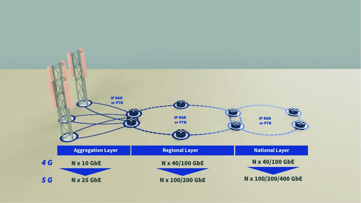
Typically metro transport network is divided into three sublayers – national or core layer, regional layer and aggregation layer. Last two layers provide transport function within different technologies – IP RAN and PTN for mobile networks, and IP packet routing/switching for fixed broadband access.

As earlier mentioned, due to ever increasing bandwidth demands for current and future metro transport network (especially aggregation level), new technologies more often and often finds their places in future infrastructure. Future metro transport network should have the related ability to carry these bandwidth demand, thus metro aggregation may provide the application scenarios for Nx100GE and Nx200GE, but metro access Nx50G (N being the system scale factor). Technologies must assure smooth migration to new capabilities by utilizing current aggregation network infrastructures, without interrupting current services.
Current “hottest” technologies in metro transport network are passive xWDM systems which utilizes 10Gbps (per channel). They are comparably low cost 18-channel system for CWDM and 80 channel 50 GHz DWDM system. These systems typically span up to 40km distance (sometimes even 60 – 80 km) with 14/15dB optical power budget. Total bandwidths are 18 x 10Gbps = 180Gbps for CWDM system and 80 x 10Gbps = 800Gbps for DWDM system. Advantages of these systems are they pure passive nature – they do not require power source. Disadvantage/Notable is that these systems needs precise calculation before choosing the right one. This includes optical power budget, channel count and future expansion possibilities prediction. Each channel has its own optical transceiver, which can transmit optical power in specific wavelength. Optical power travels through optical fiber and trough multiplexing/de-multiplexing devices containing optical prisms.
Nowadays core network and aggregation network equipment (routers & switches) has ports up to 40G/100G capable speeds. These interfaces most notably uses QSFP28 form factor transceiver. There are also CFP, CFP2 and CPAK form factors, but they are not as popular as the QSFP28 form factor, because it provides smallest size dimensions currently possible. Therefore, manufactured switches and routers are with much more ports (density) on the front panel.
In addition to 10, 40 and 100G networking, 25G and 50G Ethernet technologies are the new standards that offer significant density, cost and power benefits for server to top of rack connections. As an example we can take 40G interface. This technology in practice is four lanes at 10G speed, and it does not offer power consumption, server rack front panel port density and even cost per bit advantages. These advantages are necessary for widespread speed transition!
As the telecommunication industry continues to innovate and present higher networking speed standards like 100G, 25G interface has been developed in order to provide simpler path to speeds of the “future” like 100G and 200G. 25G standard is based on single-lane 25Gbps Ethernet link from the IEEE 100G standard (802.3bj). Currently IEEE 802.3cc standard stands for 25G application over Single Mode Fiber and 25G transceiver is realized in the same form factor as 10G transceivers – SFP. First commercial switch with 100G port interface was introduced in 2014. July, but 25G port interface switch in 2016. July.
Single-lane 25G interface chipsets use similar SERDES (serializer-deserializer) technology as 10G but delivering 2.5 times better performance, at the same time reducing power and cost per gigabit significantly. In other words – higher system bandwidth at the same power consumption if compared to equivalent 10G solution. 25G SFP standard provides higher port density than a comparable 40G solution. Power savings and higher density leads to a much lower cooling requirements and other operational expenditures.
Availability of 25G capable switches and transceivers has great impact on connectivity upgrades. Upgrading from 10G to 25G speeds is much more cost effective than upgrading directly to 40G. Upgrading to 25G Capex and Opex savings are notable, because of backward compatibility with 10G systems, rack-design and reuse of existing cabling infrastructure.
Worth mentioning that 25G interfaces are perfectly usable for 5G networks. As mentioned earlier necessary bandwidth for one 5G system antenna sector is 20Gbps. Therefore one 25G interface can perfectly utilize one 5G antenna. Base station could have incoming 100Gbps pipe leading to switching unity, which with “breakout” cable is splitted into 4x 25Gbps streams for RRU.
Current xWDM systems in metro aggregation networks around the world uses 10Gbps CWDM or DWDM optical channel links. These are limited to 10 Gbps per channel because current technological achievement only allowed to use 10Gbps SFP transceivers with different wavelength lasers (CWDM, DWDM). But now things are changing. Additionally to these 10G SFP transceivers, industry has developed four 25G CWDM SFP transceivers (1270, 1290, 1310, 1330nm), for four CWDM channels (Ask us a quote). Besides, some manufacturers are introducing 100G DWDM QSFP28 transceivers.
25G CWDM transceivers can freely substitute respective channel 10G CWDM transceivers, therefore increase total bandwidth of passive transmission system. 100G DWDM QSFP28 transceivers if they will gain popularity over time, according to specifications they will be matching same frequencies of ordinary 10G DWDM transceivers. This means they will have the same channels, and it will be possible to use them with current passive DWDM transmission systems already installed.
We have under development (not fully implemented, but you can already ask for early quotes) product which we call 100G injector. This product is “wideband/narrowband” prism, which can add or drop 1310nm 100G optical signal.

This prism, attached to any existing or newly built passive CWDM/DWDM system will utilize lowest wavelength channels. 100G injector works in 1260 nm – 1360 nm pass bandwidth. This solution is possible by using 4 LAN WDM 100G-QSFP28 transceiver, because it has more narrowly placed laser wavelengths. Currently in industry there are examples when 100G-QSFP28-LR modules signal is amplified with SOA (Semiconductor Optical amplifier) in order to accumulate mux/demux optical loses and transmit signal farther distances. This solution is not cost effective and future proof, because even now there are available 100G-QSFP28-ER (40km) transceivers that can achieve similar and even larger distances.
Conclusion:
Best technical solution for metro transport network transport is 10G xWDM system. It provides flexible link aggregation with bandwidth expansion possibilities for future. Future technological advancements introduces new optical transmission devices and new optical transceivers that can achieve higher transmission speeds – especially 25G Ethernet based devices.

