QSFP28 100G PinOut Guide
Welcome to our QSFP28 100G PinOut guide! This resource is designed for network engineers, hardware designers, and anyone interested in understanding the intricacies of QSFP28 100G connectors. You’ll find into on the functionality and usage of each pin in the QSFP28 connector.
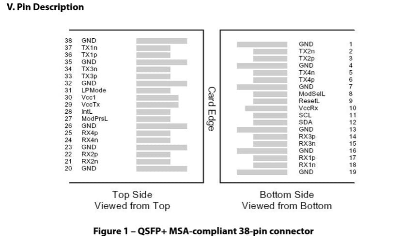
QSFP28 100G Pin Description Table
Below, we provide a detailed overview of each pin’s function in the QSFP28 100G connector:
| Pin | Name | Description | Logic | Note |
|---|---|---|---|---|
| 1 | GND | Ground | 1 | |
| 2 | TX2n | Transmitter Inverted Data Input | CML-I | |
| 3 | TX2p | Transmitter Non-Inverted Data Output | CML-I | |
| 4 | GND | Ground | 1 | |
| 5 | TX4n | Transmitter Inverted Data Input | CML-I | |
| 6 | TX4p | Transmitter Non-Inverted Data Output | CML-I | |
| 7 | GND | Ground | 1 | |
| 8 | ModSelL | Module Select | LVTLL-I | |
| 9 | ResetL | Module Reset | LVTLL-I | |
| 10 | VccRX | +3.3V Power Supply Receiver | 2 | |
| 11 | SCL | 2-Wire Serial Interface Clock | LVCMOS-I/O | |
| 12 | SDA | 2-Wire Serial Interface Data | LVCMOS-I/O | |
| 13 | GND | Ground | 1 | |
| 14 | RX3p | Receiver Non-Inverted Data Output | CML-O | |
| 15 | RX3n | Receiver Inverted Data Output | CML-O | |
| 16 | GND | Ground | 1 | |
| 17 | RX1p | Receiver Non-Inverted Data Output | CML-O | |
| 18 | RX1n | Receiver Inverted Data Output | CML-O | |
| 19 | GND | Ground | 1 | |
| 20 | GND | Ground | 1 | |
| 21 | RX2n | Receiver Inverted Data Output | CML-O | |
| 22 | RX2p | Receiver Non-Inverted Data Output | CML-O | |
| 23 | GND | Ground | 1 | |
| 24 | RX4n | Receiver Inverted Data Output | CML-O | 1 |
| 25 | RX4p | Receiver Non-Inverted Data Output | CML-O | |
| 26 | GND | Ground | 1 | |
| 27 | ModPrsL | Module Present | LVTTL-O | |
| 28 | IntL | Interrupt | LVTTL-O | |
| 29 | VccTX | +3.3V Power Supply Transmitter | 2 | |
| 30 | Vcc1 | +3.3V Power Supply | 2 | |
| 31 | LPMode | Low Power Mode | LVTTL-I | |
| 32 | GND | Ground | 1 | |
| 33 | TX3p | Transmitter Non-Inverted Data Input | CML-I | |
| 34 | TX3n | Transmitter Inverted Data Output | CML-I | |
| 35 | GND | Ground | 1 | |
| 36 | TX1p | Transmitter Non-Inverted Data Input | CML-I | |
| 37 | TX1n | Transmitter Inverted Data Output | CML-I | |
| 38 | GND | Ground | 1 |
Notes:
- GND is the symbol for signal and supply (power) common for QSFP28 modules. All are common within the QSFP28 module, and all module voltages are referenced to this potential unless otherwise noted. Connect these directly to the host board signal common ground plane.
- VccRX, Vcc1, and VccTX are the receiving and transmission power supplies and shall be applied concurrently. VccRX, Vcc1, and VccTX may be internally connected within the QSFP28 transceiver module in any combination. The connector pins are each rated for a maximum current of 1000 mA.
We hope this QSFP28 100G PinOut guide has enhanced your understanding of the QSFP28 pins. Whether you’re a network engineer or a hardware designer, this comprehensive breakdown will assist you in your projects and designs. Should you have any further questions or need additional resources, feel free to explore our other materials or contact our support team. We’re here to help with your network needs.


