100G QSFP28 module types and main differences
Nowadays world information networks have become more inter-connected than ever. This can be attributed to advancements in multiple telecommunication sectors or as OSI calls it Layers. Each layer has had an integral part in rapid development of node to node connections and technology behind it. As always, the driving part is demand by general population for exposure to data communication is higher than ever before and continues to rise as countries around the world continue their development.
At the time of writing this article in late 2019, transceiver market has shifted heavily to support 100G speeds for 100 Gigabit Ethernet (100GbE) infrastructures continued development and upkeep. Modules that support this data rate are also integral in the recent 5G and New Radio (NR) wireless communication deployment across the globe, more on that in this article.
Nevertheless, 100G connection possibilities have emerged from humble beginnings of GBIC (gigabit interface converter) through SFP, SFP+ and XFP and many other form factors that started to interconnect the world at large. Like many inventions or projects of grandeur it has taken years to polish and refine 40GbE and 100GbE which have been in research and development since late 2000s. First IEEE 802.3 communication standard to define speeds of 40 Gbit/s and 100 Gbit/s Ethernet is 802.3ba release which defined requirements and measures. Mainly defining that data transfer should be organized as separate streams of 4×25 Gbit/s or 10×10 Gbit/s lanes and physical link of MMF (Multi-mode fiber) reach up to 150 m and SMF (Single-mode fiber) reach up to 40 km.
100G is not limited to one physical form factor as many are available, for example, CFP, CFP2, CFP4, CXP and QSFP28. However, QSFP28 is most widespread and commonly used form factor for 100GbE or 100G connections in general and companies such as CISCO, Juniper and HP have implemented this in their latest hardware releases. Based on the prominence of term 100G it is important to understand thought behind QSFP28 form factor and technical jargon surrounding physical links (connection) and signal transmission technologies that are available. Few examples of industry jargon of many abbreviations are SR4, LR4, SWDM4 to name a few. Some of them can be easily understood but others require additional reading up. This is what next several paragraphs will be dedicated to.
Basics
100G QSFP28 form factor is defined by IEEE 802.3bj standard and is used to define SFF-8665 that contains requirements and guidelines important for manufacturing and further use. More detail on standards will be provided in different article.
First important physical characteristic that is defined that is transceiver connector as there are two common variations of QSFP28 module connectors referred to as LC and MPO/MTP (image 1). MPO-type connector (right side of image 1) is used for same λ, wavelengths simultaneous parallel transmission over fiber [over multiple fibers] and Double LC-type connector (left side of image 1) is used for xWDM (Wavelength Division Multiplex) technology-based transmission [over single or double fiber]. Single LC-type connector rarely used as BIDI 100G QSFP28 popularity and demand is rather low.
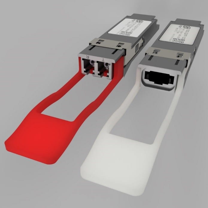
Image 1.
Second important physical characteristic that is defined is data transfer medium that connects modules which mainly are SMF, MMF and Twinaxial cabling depending on distance between nodes and coincidentally is the easiest approach to 100G QSFP28 categorization.
Twinaxial cabling (image 2) is used for PDAC (Passive Direct Attach Cables) for extra short port to port distances that commonly are less than 10 m or for ADAC (Active Direct Attach Cables) to support up to 100m long connection. Each Twinax end is attached to a transceiver electrical interface as this data transfer medium is purely electrical. Additionally, higher data rates support breakout cables with, for example, one side is 100G QSFP28 and other side is 4x25G SFP28 (image 2 100G-PDAC-QSFP-SFP).
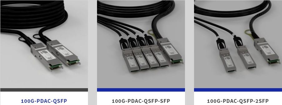
Image 2
MMF (Multi-mode Fiber) is mainly used for Short Range to Intermediate Range is different from SMF by its core diameter. As MMF has larger core diameter that allows for shorter wavelengths (λ) to be used (e.g., 850 nm). Additionally, MMF has several categories from which only OM3, OM4 and OM5 support 100G speeds for distances up to 100 m, 150 m and 150m respectively. OM5 provides additional support for BIDI (Bidirectional) data transmission that allows for a new BIDI 100G implementation.
SMF (Single-mode Fiber), as previously mentioned, has smaller core diameter and thus requires longer wavelengths of 1310 nm optimized in OS2 which provide less attenuation and dispersion and thus data transmission can be achieved for greater distances (e.g., 40 km). When talking about 100G QSFP28 over SMF transmission distances are commonly from 500 m to 10 km and Extended Range of 40 km, and with recent developments in ZR modules that can reach up to 80 km modules.
MMF based transceivers
SR4 (Short Range 4 lane) transceivers are most used in industry as it allows connections over short distances up to 150 m. Transceiver has MPO connector for transmitting data over 4 lanes and receiving data over additional 4 lanes simultaneously with data rate of 25.78125 Gbps (100GbE speed) using 850 nm wavelength. That is why 8-strand OM3 or higher MPO cable is required to link this type of transceivers.
|
Lane |
Center wavelength |
Wavelength range |
Module electrical lane |
|
L0 |
850 nm |
from 840 to 860 nm |
Tx0, Rx0 |
|
L1 |
850 nm |
from 840 to 860 nm |
Tx1, Rx1 |
|
L2 |
850 nm |
from 840 to 860 nm |
Tx2, Rx2 |
|
L3 |
850 nm |
from 840 to 860 nm |
Tx3, Rx3 |
Table 1 SR4 lane characteristics
SWDM4 (Short Wavelength Division Multiplex) transceivers use xWDM technological solution to transmit data over single fiber with each Tx/Rx having different wavelengths (L0λ = 850 nm, L1λ = 880 nm, L2λ = 910 nm and L3λ = 940 nm as visible in table 2). Transceiver has connector can differ by manufacturer but mostly are available with Double-LC connector. When compared to SR4 a major difference is that SWDM4 are scarcely available and are more expensive to produce but require less fiber to transmit and receive same amount of data as SR4.
|
Lane |
Center wavelength |
Wavelength range |
Module electrical lane |
|
L0 |
850 nm |
from 844 to 858 nm |
Tx0, Rx0 |
|
L1 |
880 nm |
from 874 to 888 nm |
Tx1, Rx1 |
|
L2 |
910 nm |
from 904 to 918 nm |
Tx2, Rx2 |
|
L3 |
940 nm |
from 934 to 948 nm |
Tx3, Rx3 |
Table 2 SWDM4 lane characteristics
SMF based transceivers
PSM4 (Parallel Single Mode 4 lane) transceivers are SMF equivalent of SR4 transceiver type as it uses MPO connector for transmitting and receiving data simultaneously using 1310 nm wavelength over 4 independent Tx lanes and same amount of different Rx lanes. Initially module was standardized for connection over OS2 for distances up to 500 m. Since then base transmission range has increased to 2 km and recently extended to 10 km. This can be attributed to advances in electrical components and reduction in optical losses.
|
Lane |
Center wavelength |
Wavelength range |
Module electrical lane |
|
L0 |
1310 nm |
from 1295 to 1325 nm |
Tx0, Rx0 |
|
L1 |
1310 nm |
from 1295 to 1325 nm |
Tx1, Rx1 |
|
L2 |
1310 nm |
from 1295 to 1325 nm |
Tx2, Rx2 |
|
L3 |
1310 nm |
from 1295 to 1325 nm |
Tx3, Rx3 |
Table 3 PSM4 lane characteristics
CWDM4 (Coarse Wavelength Division Multiplex 4 lane) are equivalent to SWDM4 transceiver type as it implements four different wavelengths for data Tx and Rx. Module has LC connector as it is similar to conventional 1G/10G CWDM MUX/DEMUX system as λ (Lambdas) in use are the same as for lower channels of ITU-T G.694.2 CWDM (L0λ = 1271 nm, L1λ = 1291 nm, L2λ = 1311 nm and L3λ = 1331 nm as visible in table 4). That is why connecting two transceivers takes up less fibers and is more efficient for use in Intermediate Distances (IR) of up to 2 km.
|
Lane |
Center wavelength |
Wavelength range |
Module electrical lane |
|
L0 |
1271 nm |
from 1264.5 to 1277.5 nm |
Tx0, Rx0 |
|
L1 |
1291 nm |
from 1284.5 to 1297.5 nm |
Tx1, Rx1 |
|
L2 |
1311 nm |
from 1304.5 to 1317.5 nm |
Tx2, Rx2 |
|
L3 |
1331 nm |
from 1324.5 to 1337.5 nm |
Tx3, Rx3 |
Table 4 CWDM4 lane characteristics
LAN WDM and also commonly referred to as LR4 (Long Range 4 lane) transceivers are commonly used in distances of 10 km and above. Compared to other xWDM solutions LAN WDM has denser channel spacing (L0λ = 1295.56 nm, L1λ = 1300.05 nm, L2λ = 1304.58 nm and L3λ = 1309.14 nm as visible in table 5) as maximum distance between channels L0 and L3 wavelengths is of 15.66 nm. This is possible by using OS2 media type that is optimized 1310 nm wavelength.Most of the previously mentioned transceiver types that are with 10 km range do require additional FEC (Forward Error Correction) feature to transmit without losses but LAN WDM can work without this feature which reduces additional costs and this serves as one of main reasons why LAN WDM is adopted quicker for distances of equal or larger than 10 km.
When talking of maximum distance for LAN WDM it is hard to say as it changes year by year. Recently market had modules with maximum range of 30km but now as demand for distance has come up modules can reach up to 40 km a ER distance more cost efficiently with latest development in ZR range of up to 80 km with relatively low BER (Bit Error Rate) and signal jitter.
|
Lane |
Center wavelength |
Wavelength range |
Module electrical lane |
|
L0 |
1295.56 nm |
from 1294.53 to 1296.59 nm |
Tx0, Rx0 |
|
L1 |
1300.05 nm |
from 1299.02 to 1301.09 nm |
Tx1, Rx1 |
|
L2 |
1304.58 nm |
from 1303.54 to 1305.63 nm |
Tx2, Rx2 |
|
L3 |
1309.14 nm |
from 1308.09 to 1310.19 nm |
Tx3, Rx3 |
Table 5 LAN WDM lane characteristics
Round up
Below is a comprehensive Table 6 that depicts module data transfer medium, data transfer technology and distance it can reach. In Table 7 is a quick overview with specific parameters and their approximate values for each module type. Additional module that are not included in this table is transceiver which is with ONLY TX or RX function with RX being used in data centers for data deep inspection or creation of asymmetric link groups.
| Abr. | Distance | MMF | SMF | ||||
| SR4 | SWDM4 | PSM4 | CWDM4 | eCWDM4 | LAN WDM | ||
| SR | 0÷100 m | ✓ | ✓ | ✓ | ✓ | ✓ | ✓ |
| 0÷150 m | ✓ | ✓ | ✓ | ✓ | ✓ | ||
| IR | 0÷500 m | ✓ | ✓ | ✓ | ✓ | ||
| 0÷2,000 m | ✓ | ✓ | ✓ | ✓ | |||
| LR | 0÷10,000 m | ✓ | ✓ | ✓ | |||
| 0÷20,000 m | ✓ | ||||||
| ER | 0÷30,000 m | ✓ | |||||
| +FEC | 0÷40,000 m | ✓ | |||||
| ZR | 0÷80,000 m | ✓ | |||||
Table 6 Possible reach distance over SMF or MMF with respective data transfer technology
|
Transceiver parameter |
|||||||||
| Data Rate per lane, Gbps | 25.78125 | 25.78125 | 25.78125 | 25.78125 | 25.78125 | 25.78125 | 25.78125 | 25.78125 | 25.78125 |
| Distance, km | 150 m*a | 150 m*a | 10 km*a | 2 km | 10 km | 10 km | 20 km | 30 km | 40 km |
| Connector | MPO/MPT | Double LC | MPO/MPT | Double LC | Double LC | Double LC | Double LC | Double LC | Double LC |
| P, W | ≤3.5 W*e | ≤3.5 W | ≤3.5 W | ≤3.5 W | ≤3.5 W | ≤3.5 W | ≤4.5 W | ≤4.5 W | ≤4.5 W |
| L0, nm | 850 | 850 | 1310 | 1271 | 1271 | 1295.56 | 1295.56 | 1295.56 | 1295.56 |
| L1, nm | 850 | 880 | 1310 | 1291 | 1291 | 1300.05 | 1300.05 | 1300.05 | 1300.05 |
| L2, nm | 850 | 910 | 1310 | 1311 | 1311 | 1304.58 | 1304.58 | 1304.58 | 1304.58 |
| L3, nm | 850 | 940 | 1310 | 1331 | 1331 | 1309.14 | 1309.14 | 1309.14 | 1309.14 |
| Optical budget,dBm* | ≈1.9÷2.4 | ≈2.0÷2.4 | ≈3.1÷6.1 | ≈4.1÷5.0 | ≈6.0÷7.0 | ≈6.0÷7.0 | ≈9.6÷12.6 | ≈13.5÷16.0 | ≈16.0÷20.0 |
| Transmitter type | VCSEL TOSA | VCSEL TOSA | DFB TOSA | DFB CWDM TOSA | DFB CWDM TOSA | DFB/EML LAN WDM TOSA | DFB/EML LAN WDM TOSA | DFB/EML LAN WDM TOSA | DFB/EML LAN WDM TOSA |
| Receiver type | PIN ROSA | PIN ROSA | PIN ROSA | CWDM ROSA | CWDM ROSA | PIN ROSA | PIN ROSA | APD ROSA | APD ROSA |
| U,V | +3.3 V | +3.3 V | +3.3 V | +3.3 V | +3.3 V | +3.3 V | +3.3 V | +3.3 V | +3.3 V |
Table 7 Transceiver parameters by type at 100GbE data transmission
- *a Distance is based on OM4/OM5.
- *b PSM4 500m, 2 km versions have less optical budget (3.1 dBm) while 10 km has around 6.1 dBm.
- *c Data rate based on 100GbE transceivers
- *d Optical budget can change transceiver by transceiver but should never be less than lower value.
- *e SR4 modules have been optimized for ≤2.5 W but ≤3.5 W are more widespread.
QSFP28 transceivers can also support InfiniBand, OTU4 and 128GFC connections and values would be similar with optical budgets would be slightly better and for this different hardware may be required (some hardware support multi-rate speeds).
Summary
In conclusion, 100G modules can differ in form factor. QSFP28 is more common and is used to support 100GbE data communication infrastructure and help with establish starting basis for 5G. It can be said that 100G is the way to go as new transmission technologies are becoming more wide spread and diverse (e.g., PAM-4) but as with everything there is a replacement on the horizon. Next generation of 200G and 400G modules that utilize, for example, QSFP-DD form factor will be used in top of the rack switches or other technological solutions that require near instant data exchange between two points and are expected to be more widely available by mid to late 2020.
Data transmission technologies such as xWDM (e.g. SWDM4, CWDM4, LAN WDM) or split lane solutions (e.g., SR4, PSM4) and mediums such as SMF, MMF or Twinaxial cabling may differ but basic principles of separate lane data streams (e.g., 4, 10) to achieve greater combined data throughput will stay and be adopted for next generation of transceiver that will support even greater speeds.
Thank you for reading!
