Step-by-Step Guide on how to perform a Loopback test on a switch port
A loopback test is a crucial tool for troubleshooting network and device problems. Loopback testing is commonly used to diagnose issues with network adapters, cables, routers, switches, and other network equipment. They can also be used to verify the integrity of signal transmissions and ensure that there are no errors or interference.
Loopback testing involves sending a signal from a source back to itself, essentially creating a closed loop. By eliminating redundant connections and interferences, with a loopback test it is possible to check and assess the functionality of the device, switch’s port, or internal configuration.
In simple terms: loopback test provides an easy way to see if the transceiver or the port of the device works properly.
When it comes to fiber loopback test with a loopback adapter, it is as simple as just plugging the loopback adapter in the optical transceiver’s ports thanks to the adapter’s form. A similar approach is with a patch cable which would act as the loopback cable.
Before you do any loopback test with a loopback adapter or a loopback cable, make sure to know what you would like to test and what metrics you would like to check during and after the tests. Common practice would be to check such metrics as transmitted signal strength and received signal strength. When you have determined the goals, you may start the test.
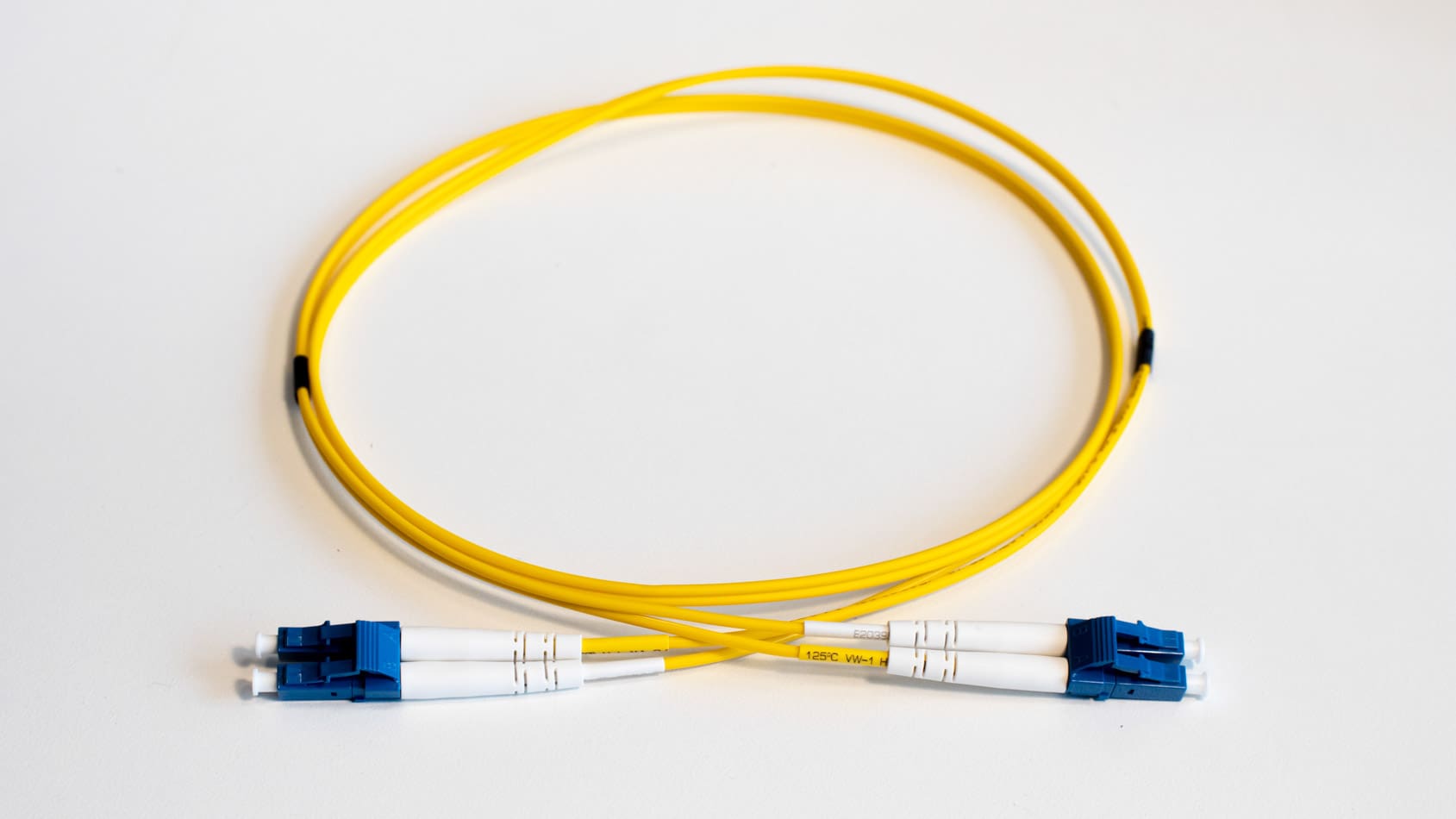
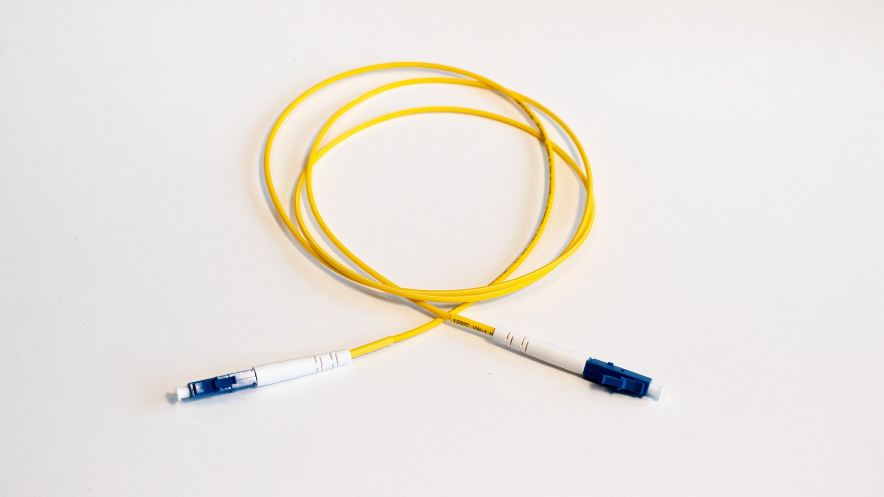
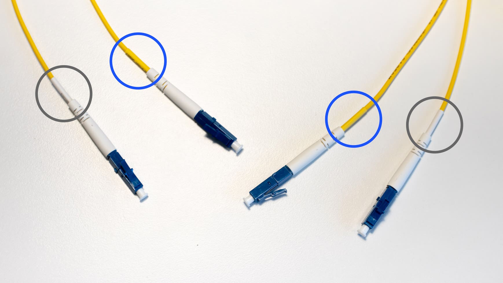
1. Get any single strand of optical patch cable with the appropriate port type (LC, SC, MTP etc.) and mode (SMF or MMF) – either a simplex cable or take a duplex patch cable and isolate both ends of the same strand of cable (you may also simply separate the duplex cable in two parts, it would just make the situation a little easier).
We advise that, if possible, it is better to use cable in such length that is suitable for the transceiver for testing, as exceeding the length may result in unwanted attenuation and, thus, issues with signal corruption. You can find the appropriate patch cables in our portfolio!
2. Insert the transceiver you would like to test in the switch.
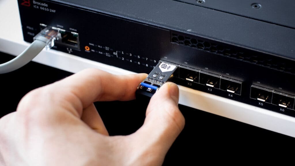
3. Insert the loopback cable into the Tx and Rx ports of the transceiver.
NB! If you are testing a transceiver with a declared high transmitting signal power level, make sure to utilize appropriate optical attenuation to preserve the receiver port in case of accidental lens burn.
The test will be initiated automatically once you close the loop with the loopback cable.
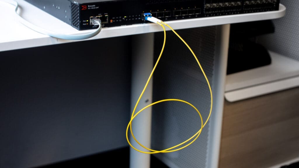
In our loopback test we are checking our 1.25G-SFP-550D in Brocade’s 6610-24F switch . The 1G LX transceiver has been coded with Brocade compatible coding to ensure proper recognition by the switch.
We insert the transceiver in Dual-mode 1/10 GbE SFP/SFP+ port 1/3/3 and, to start the test, we plug a single strand of multi-mode fiber optical patch cable (acting as our loopback cable) in both Tx and Rx ports of the transceiver.
To review how the test is going, we are looking at the DDM outputs in switch’s CLI:
ICX6610-24F Router#show media ethernet 1/3/3
Port   1/3/3: Type  : 1GE M-SX(SFP)
              Vendor: EDGE             Version: A
              Part# : 33210-100        Serial#: EO12306210947

ICX6610-24F Router#show optic 1/3/3
 Port  Temperature   Tx Power     Rx Power       Tx Bias Current
+----+-----------+--------------+--------------+-----------------+
1/3/3   37.8515 C  -002.3448 dBm -012.2257 dBm    8.402 mA
        Normal      Normal        Normal         Normal
Brocade’s 6610-24F itself already shows whether the DDM values are normal or not, including the written warning and alarm thresholds. But to be sure, we verify that the transmitted and received signal values are in line with the intervals mentioned in the transceiver’s datasheet.
| Minimum value (dBm) | Maximum value (dBm) | |
|---|---|---|
| Tx | -9.5 | -2 |
| Rx | -17 | -3 |
As we see, the transceiver’s metrics conform with the data from datasheet and affirm that the loopback test was a success.
If the test returns good results, that is, there are no errors or alarms and the signal is looping without any interruptions: everything is good, and no further action is necessary.
On the contrary, if the test fails (there is a noticeable signal power loss, port flapping or else), something is faulty and should be investigated further to single out the culprit. What could you do:
1. Start by replacing the test transceiver with another one to determine if the original transceiver was at fault
2. If the problem persists with other transceivers, check the loopback cable for any damage and replace it
3. Verify the test port configuration
4. Change the port in which the loopback test is done
Each variant and combination of them will help you easily and quickly find the part of your networking setup that causes issues.
If you have any further questions about the loopback testing or anything else in the field of telecommunications and networking, please feel free to Contact Us!

