QSFP Breakout Cable Guide
Breakout technology for cables allows a single high-speed cable to split into multiple lower-speed connections, enabling one high-bandwidth port (such as 100G or 400G) to interface with several lower-speed devices (e.g., 4×25G or 4×100G). This approach enhances network flexibility, simplifies cabling infrastructure, and supports scalable bandwidth deployment in data centers. Breakout cables are commonly used to maximize port utilization and enable cost-effective upgrades.
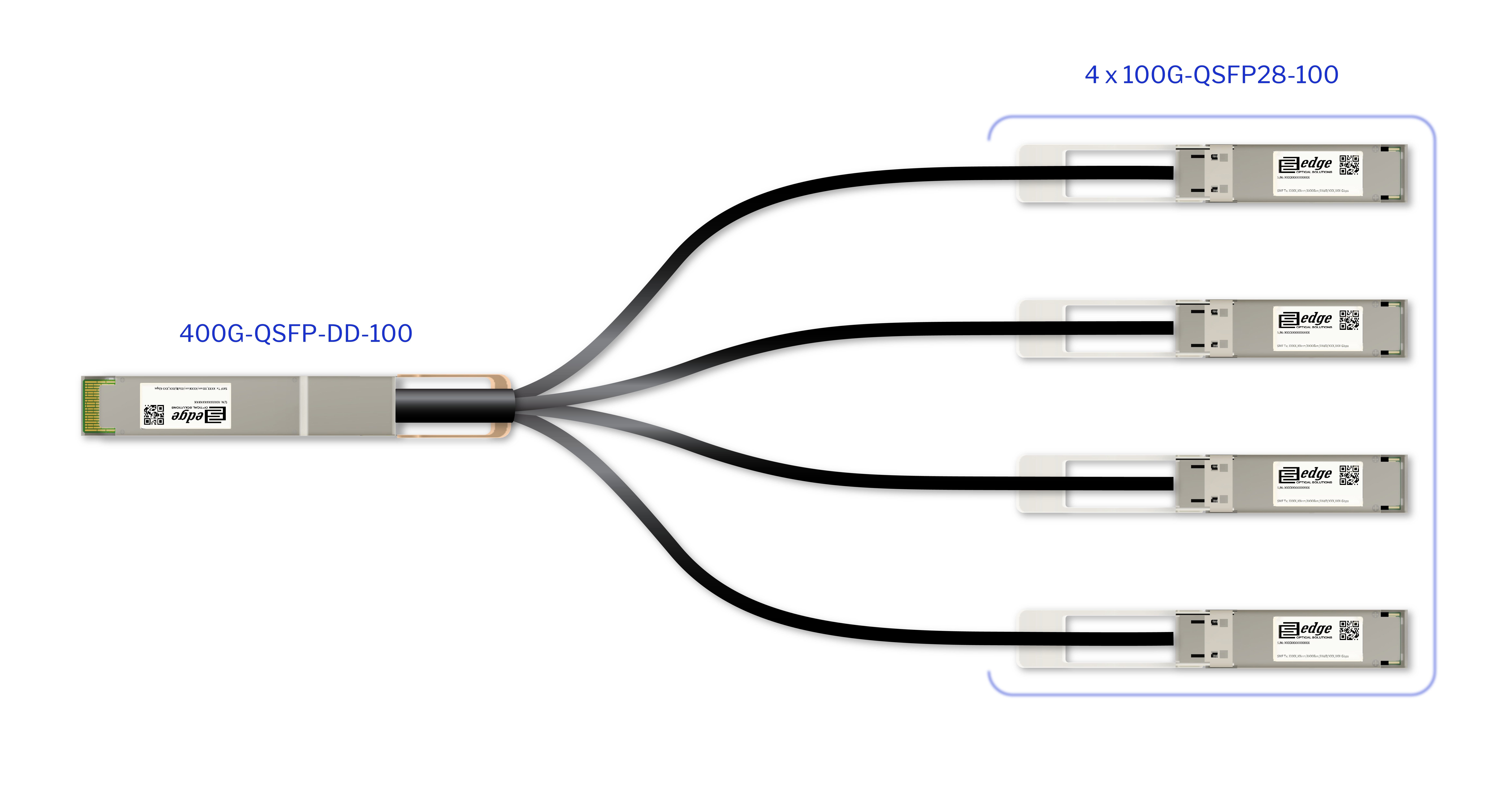
For instance, with 400G DAC or AOC breakout cables, a single 400G port on a switch can be divided into four separate 100G connections. Each of these connects to an individual 100G switch, allowing full utilization of the 400G capacity. This type of breakout setup supports smooth transitions from 100G to 400G networks while maintaining compatibility with existing 100G switches

Available breakout configurations
The QSFP breakout cables come in a variety of different configurations just to support different networking needs. Here we have listed the breakout configs from most common ones to emerging breakout options, where the copper breakout cables are terminated with optical connectors, so breakout DACs and breakout AOC. No additional connectors or cabling are required when using the copper breakout.
40G QSFP+ to 4×10G SFP+
- Our 40G-PDAC-QSFP-SFP DAC and 40G-AOC-QSFP-SFP AOC cables are one of the most widely used configurations, allowing a 40G port to connect to four individual 10G devices.
100G QSFP28 to 4×25G SFP28
- Our current standard delivered cable configuration – 100G-PDAC-QSFP-SFP. 100G to 25G considered as the standard in modern data centers. This setup offers a straightforward path for scaling up from 25G infrastructure to 100G.
200G QSFP56 to 4×50G SFP56
- This is an emerging configuration that supports higher bandwidth needs. Here it is a must that both devices interconnected has QSFP56 and SFP56 ports, as, for example, QSFP56 transceiver will not work in QSFP28 port due to electrical interface differences
400G QSFP-DD to Multiple Options
- 400G ports offer various breakout possibilities, including 2x 200G QSFP56, 4x 100G QSFP56/ QSFP28, 8x 50G SFP56, or other combinations, depending on the transceiver and cable type used. One of the most popular configurations currently is the 400G to 4x 100G QSFP56 cable.
AOC vs DAC breakout options
When choosing breakout cables, it’s important to understand the differences between DAC and AOC. Both support breakout configurations but differ in performance characteristics, physical properties, and use cases. More on the differences you can read in our technical comparison on AOC vs DAC.
In short, DAC is more used ion short distance connections and it is more cost-sensitive. AOC on the other hand is used in longer distances. It has easier cable routing.
Port mapping and lane assignments
Port mapping and lane assignment knowledge can be used for proper connectivity and troubleshooting. QSFP modules typically use four electrical lanes (from Lane0 to Lane3), and each lane carries a portion of the total data rate. In breakout setups, these lanes are divided among multiple lower-speed ports.
Lane mapping conventions
Lanes 0–3 are typically assigned in a left-to-right or top-to-bottom order, depending on the transceiver or switch. For example, in a 100G to 4×25G breakout, the mapping might look like:
- Lane 0 → Port 1 (TX/RX)
- Lane 1 → Port 2 (TX/RX)
- Lane 2 → Port 3 (TX/RX)
- Lane 3 → Port 4 (TX/RX)
where each lane carries 25Gbps data rate signal. Each lane consists of a transmit (Tx) and receive (Rx) pair. In breakout mode, these pairs are logically and physically mapped to individual SFP ports, allowing independent data paths.
Configuration Requirements
Most switches require explicit port splitter configuration to enable breakout mode. This may involve CLI commands, software-defined port modes, for example, 100G to 25G, or port group reassignments. Some platforms auto-detect the breakout cable, while others require manual intervention. Here are examples on some vendors:
| Vendor | Requires manual config? | Platform examples |
|---|---|---|
| Cisco | Yes, mostly | Nexus 9000, Catalyst 9500 |
| Arista | Yes, required | 7050X3, 7280R, 7800R |
| Juniper | Yes, flexible options | QFX5100, QFX5200 |
| Dell | Yes | S5200, Z9100 |
| Mellanox | Depends on model | SN2700, SN3700 |
| HPE | Mixed | FlexFabric, Aruba CX |
| Extreme | Yes | SLX, X465 |
In most cases, port splitter configuration is still necessary, even if the cable itself is a physical breakout cable. Even though the cable is physically designed to split a single 40G port into four 10G connections, the switch’s port must be logically configured to recognize and operate in breakout mode.
Common use cases
Now that we understand what is breakout and what kind of configurations there are in the industry, we need to understand where the multiple speed interface can be used.
- Top-of-rack to server connections. Breakout cables are often used to connect high-speed ToR switches to multiple servers. For example, a 100G QSFP28 port can be broken out into 4×25G SFP28 connections.
- Switch-to-switch port expansion. In spine-leaf or aggregation-tier networks, breakout cables allow one switch’s high-speed uplink port to connect to multiple lower-speed ports on another switch.
- Migration scenarios (40G to 10G). One of the most used variants – network transitions, such as moving from 10G to 40G or from 25G to 100G. A 40G to 4×10G breakout cable allows legacy 10G devices to continue functioning while upgrading initial infrastructure.
- Cost-effective port multiplication. Breakout cables allow network architects to maximize the usage of expensive high-speed switch ports by splitting them into multiple usable links. This eliminates the need to purchase additional switches or line cards.
- Test lab configurations. Or development environments, used to simulate production topologies or test interoperability between devices with different port speeds.

