Transceiver testing and quality requirements
Optical transceiver modules are the main end-to-end components which allows optical communication through optical fiber. Transceiver manufacturing technologies are developed over time to become faster and less susceptible to errors. Optical transceiver like any other high tech electrical appliance, during their manufacture process is undergoing firm testing and quality check procedures. These procedures are involved at each stage of transceiver manufacturing process to ensure best outcome. And if any of procedures fails, then the item is rejected and returns to production line for repeated adjustment (in case of critical fail, transceiver is removed and dismantled).
Optical transceiver manufacturing process involves a lot of steps, but the most important ones (not all accounted) which greatly affects quality of end product are as follows:
- Calibration – Tx, Rx, Eye-diagram, Voltage measurements;
- Aging test;
- Switch test;
- Wavelength and Spectrum check;
- Lens cleaning.
Calibration – Tx, Rx, Eye-diagram, Voltage measurements:
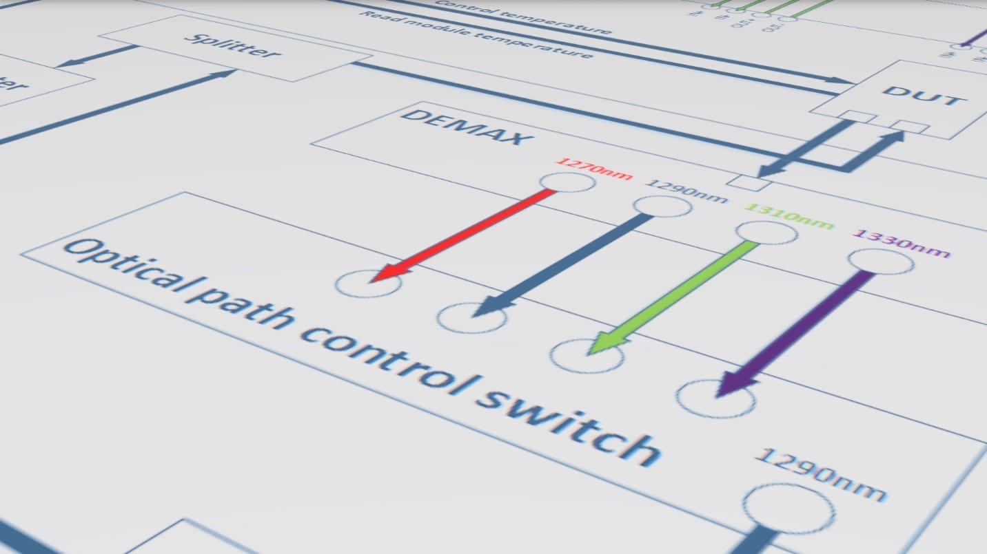
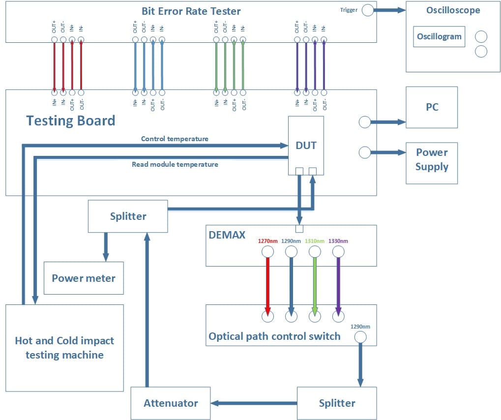
Transmitter and receiver tuning, eye-diagram and voltage level adjustment is the most crucial steps at the optical transceiver manufacturing process. These steps initially sets up transceiver for its best working parameters which complies with quality and MSA standard requirements. Transmitter power, receiver sensitivity, transmitter eye-diagram, voltage and temperature calibration and debugging process is shown in diagram 1-1. At this process Optical transceiver is described as device under test (DUT), it is connected to testing board with appropriate electrical interface for specific form factor transceiver SFP, XFP, QSFP etc. DUT transmitter is connected to de-mulitiplexing component (DEMAX) – this unit with the help of optical prisms separates optical wavelength signals which are sent from DUT QSFP LR4 optical transceiver (this transceiver uses four CWDM lines at 1270, 1290, 1310 and 1330nm (EDGE Optics, PN: 40G-QSFP-10). If DUT is SFP/SFP+ transceiver with one output wavelength, then DEMAX unit with optical path control switch is not used.
Optical Path Control Switch is unit which simply allows to select any necessary wavelength from input port and forward it to output port. This equipment uses optical switching principle which induces low (well known) insertion loss. Signal then is split, where one portion of signal is sent to oscilloscope (for eye-diagram), and other portion to power meter unit which after measurement forwards it to DUT transceiver receiving port.
DUT transmit power is measured with power meter and controlled so that it is at necessary range. Transceiver voltage measurements are done on the test board directly and results are shown on controller PC.
Temperature (hot and cold impact) testing unit is located parallel to all other measurement units, and performs DUT temperature change scenarios. What does this unit practically is heats up DUT till maximum operating temperature so that Tx, Rx and eye-diagram measurements can be taken at transceiver maximum operating temperature. And cools transceiver till the minimum operating temperature so that Tx, Rx and eye-diagram measurements can be taken again. These tests can potentially indicate problems related to DUT temperature – which if are not passed then additional calibration is performed on the affected part.
Diagram 1-1
However, testing board electrical signaling part is connected to Bit Error Rate Tester. This tester generates random signal pattern which is sent through DUT, latter analyzed with oscilloscope for eye-diagram purposes.
Eye-mask measurements and adjustments is important phase of transceivers path to best signal quality guarantee which coincides with MSA standard requirements. Eye-mask definitions specify transmitter output performance in terms of normalized amplitude and time in such a way to ensure far-end receivers can consistently tell the difference between one and zero levels in the presence of timing noise and jitter. Eye-mask measurement results indicates quality of digital signal, but does not indicate protocol or logic problems. The quality of digital signals is simple to see with an eye diagram: Bit-Error-Rate (BER) degrades with eye closure. Eye opening is indicated with yellow arrows at diagram 1-2.
MSA standard for optical transceivers indicates precise eye diagram mask (Grey rhomb drawing under yellow arrows) which should be not crossed by respective 0 and 1 signals (blue lines), and their transitions. If test signal lines crosses the eye mask, transceiver fails the test and has to undergo additional calibration. In general – more open the eye (yellow arrows), the lower chance that the receiver in transmission system will mistake a logical 1 bit for a logical 0 bit, or vice versa.
Diagram 1-2
Wavelength and Spectrum Test:
Optical transceivers has to emit precise wavelength in order to successfully communicate with their counterpart transceivers. For example simplest 10Gbps 10 kilometer (EDGE SKU: 10G-SFP-10), SFP transceiver has transmission wavelength 1310nm with possible deviation +/- 50nm and multi-mode version 10Gbps 300 meter (EDGE SKU: 10G-SFP-300) SFP 850nm with possible deviation +/- 10nm. But transceivers, like, for example 10Gbps 40 kilometer (EDGE SKU: DWDM-10G-SFP-40-21) DWDM SFP transceiver, has 1560.61 nm wavelength with +/- 0.8nm deviation. This DWDM transceiver especially has to be with precise laser output wavelength, because it should not crosstalk with other side channels due to system design principle.
During optical transceiver manufacturing wavelength precision is measured with spectrometer (Drawing 1-3). Transceiver is plugged in electrical power source – mostly in factory environment it is special powered PCB or a network device switch as used in this example. This graph represents 1Gbps 10 kilometer transceiver (EDGE SKU: 1.25G-SFP-10D). At spectrograph we can see X axis as wavelength, and Y axis power. The power peak forms a sharp form and is located at 1310.56nm (at -3.16dBm), it is very close to MSA standard regulation 1310.00nm – so we can say this module has passed the spectral test.
In case if DUT has power peak at different wavelength which is not consistent with MSA regulation, then this transceiver is discarded as defective!
Diagram 1-3
Lens Cleaning:
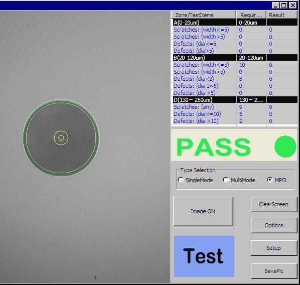
During transceiver manufacturing process, after each testing step optical transceiver lenses are checked for dirt and scratches, and cleaned if necessary. It is due to fact that each testing procedure involves connecting equipment to transceiver optical parts, and therefore it is susceptible to dirt. Before cleaning procedure each transceiver lens is firmly checked by microscope. Picture of microscope test output can be seen in diagram 1-4.
Diagram 1-4
If there are no scratches or dirt’s on lens core and its cladding, then this test is positive. Otherwise cleaning procedure is performed. Cleaning procedure removes dirt`s, oils and other foreign bodies/substances. So that after cleaning another microscope test is performed. Of course if core has damages like for example scratches then this transceiver is rejected and dismantled.
Summary:
Optical transceiver manufacture process involves a lot of important steps. Most important ones are at the transceiver manufacturing first stage, when the key elements are soldered and powered on for the first time – for calibration purposes. Calibration stage is crucial because it determines how transceiver will perform for the rest of his life. If transceiver delivers bad performance at calibration stage, then the safest step would be to discard this unit. Other tests which are performed on transceiver after calibration stage can indicate potential problems and weakest points. Aging test and switch test are the perfect tests for indicating that exact transceiver will have problems in long term. Transceiver lens cleanness is important factor because, if lens is damaged by dirt, oil, or scratched, then this can cause issues in long term. Like for example, increased laser deterioration and burnout.


