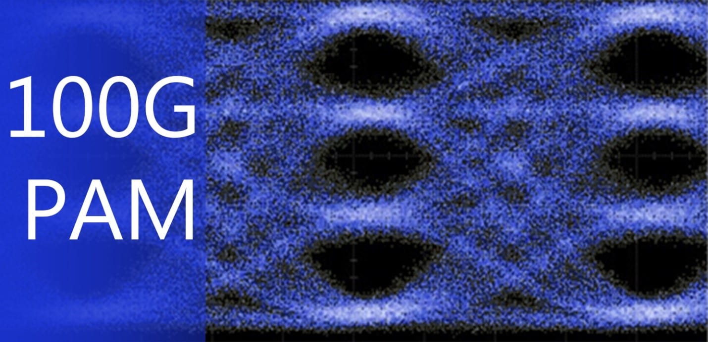
100G Single Lambda (100G PAM & Single Lambda)
100G PAM (Pulse Amplitude Modulation) are gaining ground in transceiver market and is encouraged by many but is it THE future? Many also say that future perspectives are grand, full with optimism as this technology is embraced by CISCO, HUAWEI, ARISTA to name a few. Hence, this article will go over the importance, pros and cons of PAM and technology behind it, and how it can and will change transceivers.
As term PAM-4 is only shortly mentioned at the end and is not included in the previous article named “100G QSFP28 module types and main differences” which purpose is to deepen knowledge in 100G and includes information regarding – QSFP28 form-factor, industry jargon, incorporated data transmission technologies and differences between them. PAM has to receive additional attention and a separate entry as this is a worthwhile topic that deserves an article of its own.
Pulse Amplitude Modulation and Pulse Width Modulation (PWM) have been used for many decades and are the corner stones for signal modulation that allows to create custom signal/wave forms and manage duty cycles. This is used in multitude of industries that include electronics for added power saving and efficiency. Added bonuses for well-modulated units is the protection against overworking, overload and unwanted noise. Only negative is that sometimes control circuit is more complex than system itself and requires additional power for operation.
Both PAM and PWN are implemented in telecommunications at large as they are the building blocks for mobile and data transmission networks and ensure worldwide connection across the globe. This raises a question “Why transceivers are lacking PAM implementation for data transmission?” and it is well placed. This can be answered in two ways. Either market has no need for it or technological solution is not economically sufficient.
Either answer is correct. Only few could have foreseen this enormous expansion in data amount and computing power. That is why telecoms, carrier networks and data centers have to invest heavily in infrastructure to support demand on an ever-growing scale that is increasing and not showing any signs of lessening. Additionally, majority of data circulation is video steaming and voice/video calling that uses more data then surfing the Web and more susceptible to latency and data loss. This demand has to be supplied.
As for technological solution which was available at the start of the previous decade when people were still transitioning from flip phones to smartphones and Windows 7 was the great new thing to surpass XP and IEEE 802.3ba containing 40GbE and 100GbE specifications is to be released soon, to say it was lacking is to put it kindly at best.
However, advancement has been significant all across the globe and in all fields. This has yielded the result needed. Electrical components have shrunk in size, reduced heat dissipation, increased computation and throughput. Thus, transceivers are enabled to modulate transmitted optical signal via DSP (digital signal processor) and surpass encoding in 0s and 1s which is implemented in NRZ (Non-Return-to-Zero) and other pre-PAM encoding schemes. This approach of PAM has reduced complexity of optics used in a transceiver design.
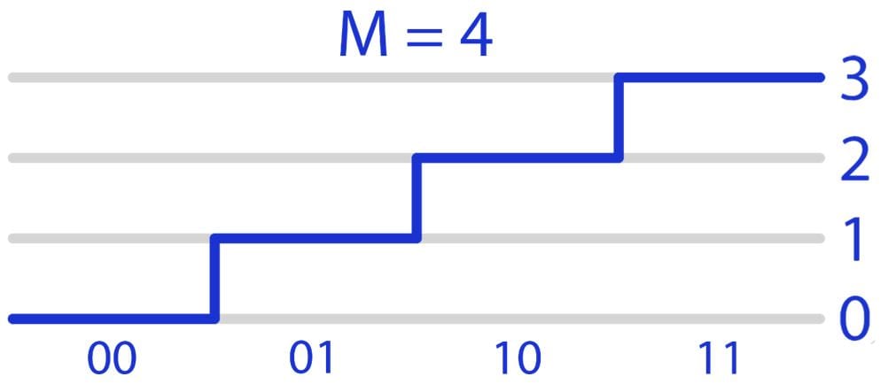
Furthermore, when comparing NRZ with PAM it is clear that the later provides more flexibility than ever before. NRZ encoding scheme can transmit using voltage level representing either a 0 or a 1 and caps out at 28.9 Gbps while PAM4 can transfer data at up to 57.8 Gbps. By design PAM can encode signal in range from 0 to theoretically infinity, which is farfetched of course. At the time of this article PAM can encode in range from 0 to 3 at best. Nevertheless, significant data throughput increase is seen when using PAM that uses 4-level MLS (Multi-Level Signaling) using signal value from 0 to 3 as visible in image below.
This 4-level approach effectively allows to transfer two bits at the same time as 2-level (0 and 1) allows for a single bit transfer. Thus, information can be packed denser and thus increasing throughput up to two times. From power saving and transmission efficiency perspective, at low data rates like 1G benefit is not noticeable and only at 10G and up start to become relevant.
Additionally, Nyquist frequency present is half of NRZ at the same data rate which results in lower channel-dependent loss, noise power spread and higher channel resolution.
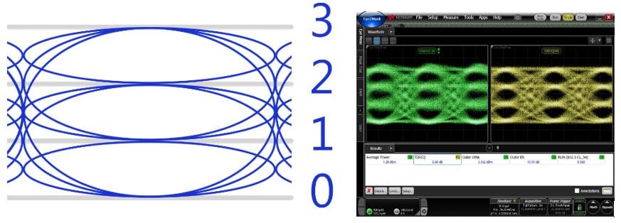
However, a down side of PAM4 is worse SNR (Signal-to-Noise Ratio) that is caused by tighter spacing between voltage/signal levels. Voltage levels are equally separated apart from one another and are one third (1/3) of an NRZ voltage level (depicted in image below and to the left).
This places a greater quality requirement on transceivers and their testing, more on this can be read more about in a recent article “Transceiver testing and quality requirements”. For data transmission and recognition, the most important test is Eye-diagram which is performed via an oscilloscope (visible in image above and to the right). When referring to PAM, introduction of 2 additional signal levels tightens eye height and thus parameter that reflects combined signal symmetry in range from 0 to 1 or from 0 to 100 – Eye Mask Linearity MUST be 0.95 or 95 accordingly and higher to be acceptable. This is a must as lower values will cause signal level overlaps or misreads. To avoid SNR drawback and increase Eye Mask Linearity, PAM based designs will consume more power to increase output signal power (dBm) and to power FEC (Forward Error Correction) which implementation will be mandatory.
Practical appliance of PAM based transceivers have started in last few years and implements MPO working principle of old. Where NRZ uses 25G transmission, PAM provides 50G and is standardized by IEEE 802.3cd for 50G, 200G, 400G. Thus, 4 separate lane data streams can be upgraded from 100G to 200G is possible. Similar to 100G module naming is consisting of speed + formfactor + distance + number of channels (depending on multiplier of 50) naming matrix for 50G PAM is in table below.
| 50G Base PAM SKU Matrix | |||
|---|---|---|---|
| Speed | Form Factor | Distance | Channels |
| 50G | QSFP28 | SR | (1) |
| 100G | QSFP-DD | FR | 2 |
| 200G | QSFP56 | LR | 4 |
| 400G | OSFP | ER | 8 |
| 800G | CFP8 | ZR | 16 |
For example, 50G over 8 channels and at distances of 10 km while using QSFP56 form factor will have a SKU of 400G-QSFP56-LR8.
As for technical execution, it will have different channel count, depending on lines used but principle of DSP use for signal generation and receiving will be implemented in all.
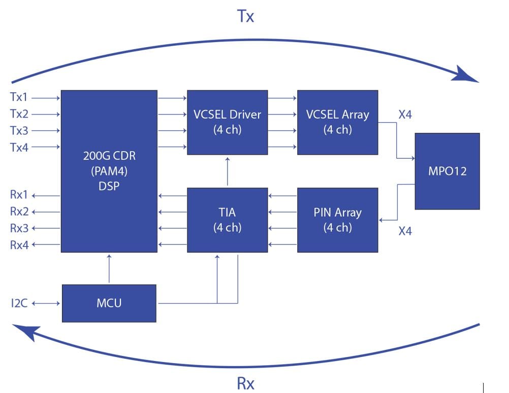
For example, below is a 200G-QSFP56-SR4 electrical block diagram.
Receiving data signal (Rx):
Incoming optical data signal passing through MPO-12 connector is received by PIN Array (ROSA) and forwarded to TIA (Transimpedance Amplifier) to reduce SNR value. Then signal is forwarded to a DSP (digital signal processor) where optical 4-level MLS is received and converted to electrical signal that is forwarded to card’s edge (electrical connector).
Transmitting data signal (Tx):
Outgoing electrical signal is received by card’s edge (electrical connector) and is forwarded to DSP for electrical to optical signal conversion. Optical signals are received by VSCEL drivers which after MCU instruction forward data signal to VSCEL Array. VSCEL Array creates light emission (Tx) that is forwarded through MPO-12 connector into optical fiber.
Other diagrams will depict similar signal conversion and forwarding. Main differences are differing in number of Tx and Rx lanes and connector. MPO/MTP connector are to be used when channel count for Tx and/or Rx is above 1 (LC will be used) and only difference would be by number connection lines as MPO-12, MPO-16 or MPO-24 based on data rate and lanes in use.
Nowadays, popularity is gaining 4 channel PAM approach which as previously mentioned allows for 200G-PAM4 data links and PAM-8 for 400G communication which utilizes 50G base rate. These transceivers are slowly gaining market share and by late 2020 should be widely sought after but most likely not for long. Even though this is amazing industry is looking to make even greater strides in data transmission and replace 50G base rate with 100G to lead the future to come of 400G and 800G.
Of course, this is amazing but it has to be standardized to remove possibility of mismatches when pairing different OEM hardware as IEEE 802.3ck is not yet released. That is why in recent years a new MSA group has appeared.
The 100G Lambda Multi Source Agreement (MSA) Group has released 100G-FR/LR requirements and guidelines to define and standardize manufacturing (as requirements are fairly new, they can be a subject to change). It is proposed to use 4×26.5625 Gbps, 2×53.125 Gbps or 1×106.25 Gbps signal rate in two lanes in each direction per lane. For easier part number identification below is SKU matrix to be used based on different channel count.
| Type | Data rate per line, Gbps | Number of lanes | 100G-PAM Transceiver SKU/PN | |||
|---|---|---|---|---|---|---|
| PAM | 106.25 | 1 | 100G-QSFP28-DR | 100G-QSFP28-FR | 100G-QSFP28-LR | 100G-QSFP28-ER |
| PAM2 | 53.125 | 2 | 100G-QSFP28-DR2 | 100G-QSFP28-FR2 | 100G-QSFP28-LR2 | 100G-QSFP28-ER2 |
| PAM4 | 26.5625 | 4 | 100G-QSFP28-DR4 | 100G-QSFP28-FR4 | 100G-QSFP28-LR4 | 100G-QSFP28-ER4 |
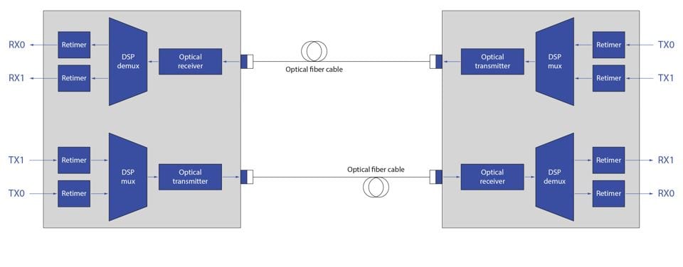
The Goal is 100G-PAM as 100G-PAM2 will be the same 50G base over two lanes. The 100G-PAM is challenging but can be done when using a MUX/DEMUX units. Approach can be to take two 50G signals and multiplex into 100G data signal and demultiplex this signal at receiver’s end. As visible in block diagram below and can be applied to higher data rates.
As only few offer and 100G-PAM and majority of manufacturers are to hit end of R&D and testing by mid to late 2020 this transceiver will remain with a high market price for next year or even more. For now, reaches of 100G-PAM supporting transceivers are divided by Distances and abbreviation are DR and is up to 500 m, FR and is up to 2 km, LR and is up to 10 km and ER is up to 40 km.)
For now, 50G base rate PAM is to be used but come 2021 and with wider supply of 100G base rate PAM transceiver will shift towards this technology and be as a base for future data interconnections.
Concept of 400G seemed futuristic and excessive. However, announcement of 5G roll out and wide scale industrialization of countries like India has made futurism today’s reality. This is why many are already looking past 100G, 200G and 400G and reach for 800G and 1600G and PAM is the number one candidate to achieve goal. Many obstacles are in the way but progress always finds a way to make dreams reality and make technology look like magic.

