CFP Optical Transceiver: The Basics
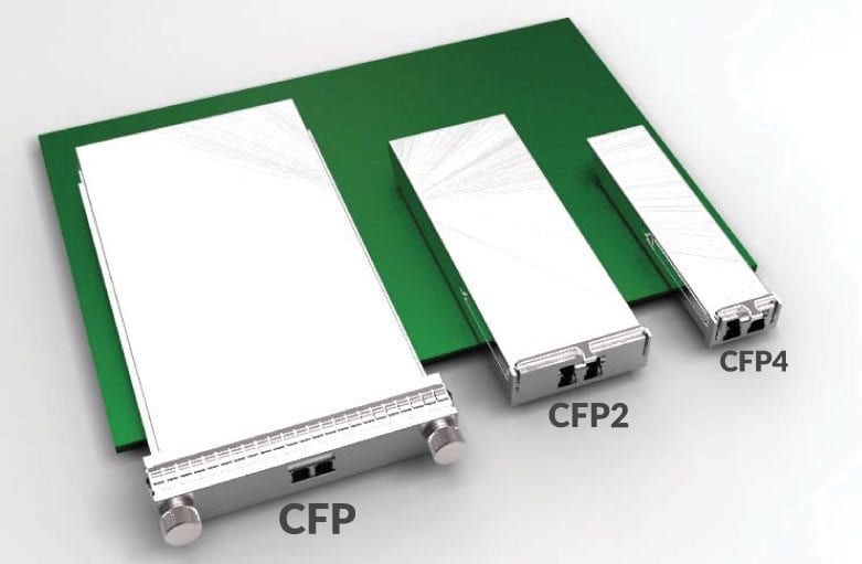
The CFP module is a hot pluggable form factor designed for optical networking applications. CFP is acronym from 100G (C = 100 in Roman numerals; Centum) Form factor Pluggable. As name suggests, CFP is introduced to serve as optical transceiver for 100G interfaces. There are several CFP types introduced – CFP, CFP2 and CFP4, but let’s begin with general CFP architecture. General CFP architecture of CFP divides in two parts – Electrical interface interacting with equipment line card interface and optical line interface.
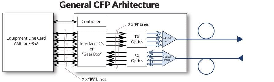
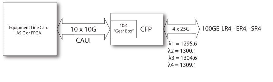
From equipment line card electrical interface aspect CFP has several “M-Lines” with are working 10Gbps speed and separate management interface used for clock & signaling data. If CFP is working 100GBase-LR4 mode, then it has 10 x 10Gbps M-Lines, if 40GBase-LR4 mode, then 4 x 10Gbps M-Lines. So called “Gear Box” is electrical 10:4 Mux/DeMux module aggregating up to 10 M-Line interfaces in maximum 4 N-Line interfaces. In case of 100GBase-LR4 each N-Line speed is 25Gbps and in case of 40GBase-LR4 N-Line speed is 10Gbps. Each N-Line is converted to optical signal with different wavelength and all four wavelengths are transmitted to CFP line interface using built in passive optical multiplexers.
CFP form factor is oldest from CFP family and it has current MSA (Multi Source Agreement) Rev 1.4. It can support both – 100GBase-X and 40GBase-X, and it’s general principle is following:
CFP electrical interface for 100G transmission is called CAUI – C (it again represents Roman Centum for 100G) Attachment Unit Interface. CAUI interface was standardized by IEEE802.3ba – Annex 83A, defining that CAUI interface is a parallel electrical interface with each lane running at a nominal rate of 10.3125 Gbps.
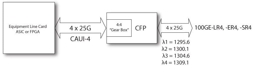
On February 16, 2015, the 802.3bm standard was approved. The 802.3bm standard specifies four-lane chip-to-module and chip-to-chip electrical specification (CAUI-4). In new version of CAUI-4 interface are 4 M-Lines, each running speeds 25.78 Gbps for 100G Ethernet and 27.95 Gbps for SONET/SDH OTU4.
| Check out our 100G CFP Portfolio: |
|
100G CFP
|
Popular 100G Port implementations using CFP Modules:
- 100GBASE-SR10 – IEEE Standardized CFP Module using special MPO interface/cable with ten parallel optical fiber pairs (MTP24), each running at 10.31 Gbps and using 850nm lasers. It’s possible to achieve up to 150m.
- 100GBASE-SR4 – CFP Module using special MPO interface/cable with four parallel optical fiber pairs (MTP12), each running at 25.78 Gbps and using 850nm lasers. It’s possible to achieve up to 150m.
- 100GBASE-LR4 – IEEE Standardized CFP Module using standard LC dual fiber interface with single mode cable, but running four optical wavelengths each direction (1295.56 nm, 1300.05 nm,1304.59 nm, 1309.14 nm) and muxing/demuxing of these wavelengths happening inside CFP module. Each wavelength is running at 25.78 Gbps and it is possible to achieve up to 10 km. Such formations of four wavelengths sometimes is referred also as LAN-WDM.
- 100GBASE-ER4 – IEEE Standardized CFP Module using standard LC dual fiber interface with single mode cable, but running four optical wavelengths each direction (1295.56 nm, 1300.05 nm,1304.59 nm, 1309.14 nm) and muxing/demuxing of these wavelengths happening inside CFP module. Each wavelength is running at 25.78 Gbps and it’s possible to achieve up to 40 km.
- 100GBASE-ZR – Proprietary standard (Juniper for example) CFP Module using standard LC dual fiber interface with single mode cable, but running 193.90 THz (+/-1.8 GHz) / 1546.119 nm DWDM wavelength with Dual polarization-quadrature phase shift keying (DP-QPSK) with forward error correction (FEC), or other words it’s Coherent Optics transmission. Each phase-shifted/polarized wavelength is running at 25.78 Gbps and it’s possible to achieve up to 80 km.
This is basic introduction of CFP first generation optical transceivers, and in some future posts we will try to cover CFP2 and CFP4 form factors and their implementations.
