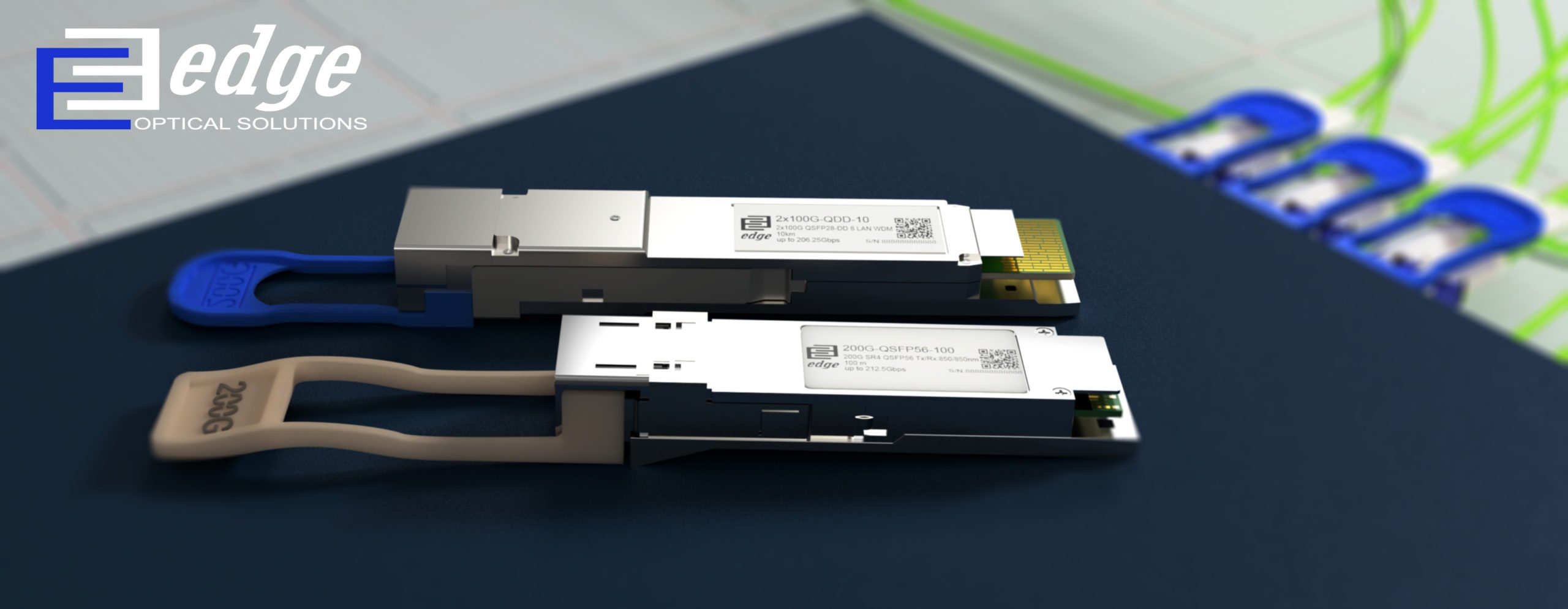
QSFP-DD vs QSFP28/QSFP56 – What Are The Differences?
- QSFP-DD vs QSFP28 / QSFP56 Quick Overview
- Difference 1 – Data Rate
- Difference 2 – Modulation Type
- Difference 3 – Power Consumption
- Difference 4 – Connector Types
- Difference 5 – Dimensions
- More on QSFP-DD Form Factor and Module Types
- More on QSFP56 Form Factor and Module Types
- More on QSFP28 Form Factor and Module Types
- Conclusion
Intro
QSFP-DD vs QSFP28 / QSFP56 how we got here with so many different QSFP’s ? The rapid growth of cloud data center networking and interconnections are pushing the technology development to meet the ever higher bandwidth connectivity demands. From the rise of 40G-QSFP transceivers and ever successful advancement to the 100G-QSFP28 form-factor, the next major step is prevalence of 200G and 400G Ethernet technology with QSFP-DD form-factor optical transceivers.
Current widespread use of 100G QSFP28 technology transceiver form-factor, followed by 200G QSFP56 transceiver form-factor, have led to a completely new optical transceiver form-factor QSFP-DD.
Confused? Yep, it is a bit, this article will help to quickly understand the main differences between QSFP-DD, QSFP56 and QSFP28.
1. QSFP-DD vs QSFP28 / QSFP56 Quick Overview
| Form Factor | QSFP-DD | QSFP56 | QSFP28 |
|---|---|---|---|
| Data Rate | 400G/200G | 200G | 100G |
| Lane count | 8 electrical | 4 electrical | 4 electrical |
| Lane data rate | 25 / 50 Gbps | 50 Gbps | 25 Gbps |
| Modulation type | NRZ / PAM4 | PAM4 | NRZ |
| Power consumption | 12 W | 4 – 7.5 W | < 3.5 W |
| Connector types | CS / LC | LC / MPO / CS | LC / MPO |
| Dimensions | 18.35 / 89.4 / 8.5mm | 18.35 / 72.3 / 8.5mm | 18.35 / 72.3 / 8.5mm |
2. QSFP-DD vs QSFP28 / QSFP56 Difference 1 – Data Rate
The first basic parameter which describes optical transceivers is data rate. Data rate is defined as the amount of data transmitted during a specified time period over a network. Different transceivers and respective networking technologies have different data rate values.
QSFP-DD has the maximum data rate 200Gbps or 400Gbps depending on signal modulation technology used. Its main difference when compared to QSFP56 or QSFP28 is that QSFP-DD name states – double density, this means that its electrical lines are doubled from 4 to 8.
- 8 channels modulated with NRZ results of 25Gbps per channel, which totals to 200Gbps.
- But 8 channels modulated with PAM4 results in 50Gbps per channel, which totals to 400Gbps.
(Respectively, QSFP56 maximum data rate is 200Gbps, but QSFP28 is 100Gbps).
Comparison of data rates basing on networking technologies:
- Ethernet technology standartizes following data rates for QSFP-DD – 212.5 Gbps, 425 Gbps.
- InfiniBand is an industry standard, channel-based, switched fabric interconnect architecture for server and storage connectivity. InfiniBand standartizes following data rates for QSFP28: 100G EDR, for QSFP-DD: 200G HDR, 400G NDR.
- The optical transport network (OTN) make up a generic Layer-1 transport network, enabling different service types to coexist and share the same infrastructure transparently, without affecting each other’s performance.OTN Optical Transport Network, specifies OTU4 for QSFP28 100G, OTUc2 for 200G, OTUc4 for 400G applications, QSFP-DD respectively.
Fiber Channel: 128GFC (24850 56.1 PAM-4) released in 2021, with more higher data rate generations to be released in future – 256GFC at 2024.
Summary:
| QSFP-DD | QSFP56 | QSFP28 | |
|---|---|---|---|
| Ethernet | 212.5Gbps, 425Gbps | 212.5Gbps | 106.25Gbps |
| InfiniBand | 400G NDR, 200G HDR | 200G HDR | 100G EDR |
| OTN | OTUc4, OTUc2 | OTUc2 | OTU4 |
| Fiber Channel | – | – | 128GFC |
3. QSFP-DD vs QSFP28 / QSFP56 Difference 2 – Modulation Type
Next notable difference factor is transceiver modulation. Optical transceiver consists of a laser which is able to emit light, and a modulator. Optical modulator is a device which can be used for manipulating a property of light. It determines the quality of transmissions between transmission equipment.
Regarding pluggable optical transceivers, it is the intensity of the light that is modulated. Engineers have long utilized non-return to zero (NRZ) modulation for 1G, 10G and 25G, using host side forward error correction (FEC) to enable longer distance transmissions. For higher data rate 40G and 100G industry introduced signal parallelization of 10G and 25G NRZ modulated signals. In short lower speed optics 1G, 10G, 25G and most 100G optics, modulates the intensity of the light at NRZ two levels, and is therefore binary.
Downside for NRZ modulation technology for 200G, 400G and other faster data rates is not efficient as compared to smaller data rates. As a result, network scientists have developed PAM4 modulation for these high bandwidth data rates.
Different modulation technologies:
NRZ – Non-Return-to-Zero, is a 2 level binary code using low and high signal levels to represent the 1/0 information of a digital logic signal. NRZ can only transmit 1 bit, i.e. a 0 or 1, of information per signal symbol period.
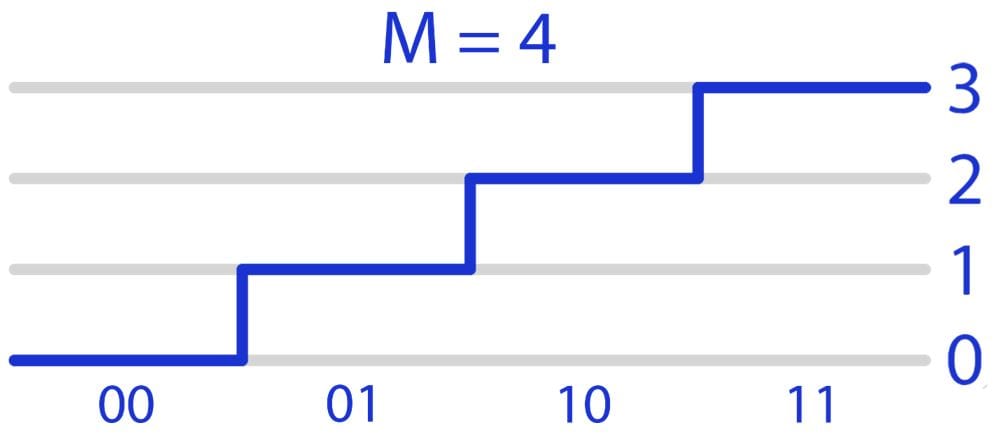
PAM4 – Pulse Amplitude Modulation 4 is a 4 level signal modulation format used to transmit signals. Each signal level can represent 2 bits of logic information.
This means that with PAM4 modulation information can be transmitted in two times shorter time. Or two times more information at the same time.
Practically we can see this with a 400G transceiver. This transceiver has a built in DSP gearbox which takes 8x 25GBaud PAM4 signal and converts it to 4x 50GBaud PAM4 signal. And so that it is with PAM4 modulation 4x 50GBaud scales to 4x 100Gbps lines, which then are multiplexed and fully gives 400Gbps data rate.
Picture – PAM4 four distinct levels to encode 2 bits of data:
Summary:
| Transceiver type | Modulation |
|---|---|
| 100G QSFP28 | NRZ |
| 200G QSFP56 | NRZ / PAM4 |
| 400G QSFP-DD | PAM4 |
4. QSFP-DD vs QSFP28 / QSFP56 Difference 3 – Power Consumption
Optical transceiver power consumption is closely related to host device total power budget. The bigger the transceivers power consumption, the smaller count of transceivers usable in host equipment. So the smaller power consumption of transceiver and host equipment altogether – the better performance and smaller environment impact.
QSFP-DD transceiver specification allows maximum power consumption of 12 Watts.
QSFP56 transceiver specification allows maximum power consumption of <5 Watts.
QSFP28 transceiver specification allows maximum power consumption of <3.5 Watts.
General rule of thumb, the smaller the power consumption the smaller the module temperature, better transceiver reliability and better overall performance of transceiver.
Summary:
| Transceiver type | Power consumption |
|---|---|
| 100G QSFP28 | <3.5 Watts |
| 200G QSFP56 | <5 Watts |
| 400G QSFP-DD | <12 Watts |
5. QSFP-DD vs QSFP28 / QSFP56 Difference 4 – Connector Types
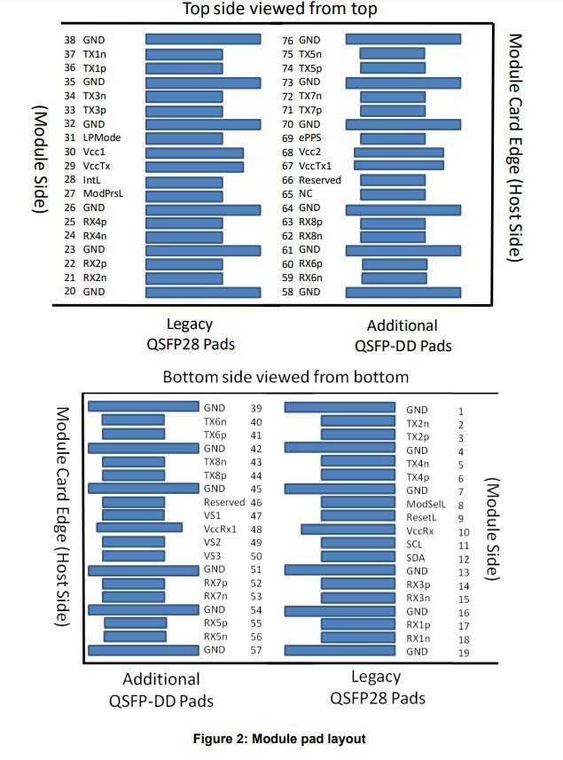
Optical transceivers have two ends. One end is the electrical connector which connects to the host equipment (switch, router etc..) other end is laser output which connects to optical fiber. QSFP28, QSFP56 transceivers have a 38pin electrical interface which connects to the host device. But QSFP-DD as it is double density, has a double count of electrical pins – 76. This basically means that systems (host devices) which are designed with QSFP-DD port are backward compatible with QSFP56 and QSFP28 form factor transceivers. Practically this means that if you have an router with QSFP-DD ports, you can easily plug QSFP56 or QSFP28 in those same ports (before connecting check product data sheet if port logically supports QSFP56 or QSFP28 transceiver).
Following picture shows us QSFP28 pads and additional pads which are used for QSFP-DD, to accommodate the double line interface.
Optical transceivers on their respective ends have an optical connector compatible plug mechanism of female type. This connector can have the following type: LC, MPO or CS. Regarding the MPO cables we at EDGE Optics have separate article about MPO and MPT cables.
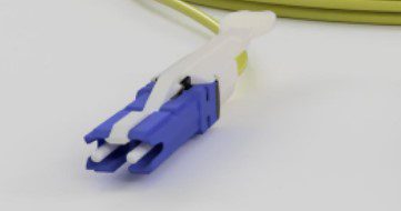
CS connector is the newest generation technology for connecting 200G and 400G optical interfaces. The CS connector consists of a Double LC type push-pull coupling mechanism which is by 40% smaller than our well known Duplex LC connector. The smaller footprint doubles up the connector density on the switch front panel if compared to LC connector.
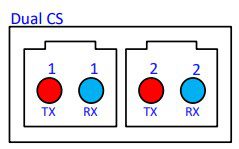
One QSFP-DD transceiver takes two CS connectors, one pair for transmission and one pair for receiving signals.
Dual CS connector profile:
CS connector:
| Transceiver type | Connector |
|---|---|
| 100G QSFP28 | LC / MPO |
| 200G QSFP56 | LC / MPO / CS |
| 400G QSFP-DD | LC / CS |
6. Difference 5 – Dimensions
QSFP-DD is the latest developed and with highest data rate transceiver, it has some dimension differences if compared with QSFP56 and QSFP28 form factor transceivers. QSFP-DD is a slightly longer transceiver because of four extra electrical lines – which makes it a double density transceiver (the electrical interface contains a larger count of electrical pads – 76).
QSFP-DD 18.35 / 89.4 / 8.5mm
QSFP56 18.35 / 72.3 / 8.5mm
QSFP28 18.35 / 72.3 / 8.5mm
7. More on QSFP-DD Form Factor and Module Types
| Type | Fiber type | Wavelength | Number of lines | Reach | Optical modulation | Optical connector |
|---|---|---|---|---|---|---|
| 400GBASE-SR8 QSFP-DD | MMF | Tx/Rx 850/850nm | 8x53Gbps | 100m (OM4) | PAM4 | MTP/MPO |
| 400GBASE-DR4 QSFP-DD | SMF | Tx/Rx 4×1310 PSM4 | 4×106.25 Gbps | 500m (OS2) | PAM4 | MTP/MPO |
| 400GBASE-DR4+ QSFP-DD | SMF | Tx/Rx 4×1310 PSM4 | 4×106.25 Gbps | 2km (OS2) | PAM4 | MTP/MPO |
| 400GBASE-FR4 QSFP-DD | SMF | Tx/Rx 4 CWDM lanes:1271, 1291, 1311, 1331. | 4×106.25 Gbps | 2km (OS2) | PAM4 | LC |
| 400GBASE-LR4 QSFP-DD | SMF | Tx/Rx 4 CWDM lanes:1271, 1291, 1311, 1331 | 4×106.25 Gbps | 10km (OS2) | PAM4 | LC |
| 400GBASE-ER4 Lite QSFP-DD | SMF | Tx/Rx LAN WDM lines: 1295.56, 1300.05, 1304.58, 1309.14 | 4×106.25 Gbps | 40km (OS2) | PAM4 | LC |
| 400GBASE-LR8 QSFP-DD | SMF | Tx/Rx 8 LWDM lanes:1273, 1277, 1282, 1286, 1295, 1300, 1304, 1309 | 8x53Gbps | 10km (OS2) | PAM4 | LC |
| 400GBASE-ER8 QSFP-DD | SMF | Tx/Rx 8 LWDM lanes:1273, 1277, 1282, 1286, 1295, 1300, 1304, 1309 | 8x53Gbps | 40km (OS2) | PAM4 | LC |
| 200GBASE-LR4 QSFP-DD | SMF | Tx/Rx LAN WDM lines: 1295.56, 1300.05, 1304.58, 1309.14 | 4x53Gbps | 10km (OS2) | PAM4 | LC |
| 200GBASE-ER4 QSFP-DD | SMF | Tx/Rx LAN WDM lines: 1295.56, 1300.05, 1304.58, 1309.14 | 4x53Gbps | 40km (OS2) | PAM4 | LC |
8. More on QSFP56 Form Factor and Module Types
| Type | Fiber type | Wavelength | Number of lines | Reach | Optical modulation | Optical connector |
|---|---|---|---|---|---|---|
| 200GBASE-SR4 QSFP56 | MMF | Tx/Rx 850/850nm | 4x53Gbps | 100m (OM4) | PAM4 | MTP/MPO |
| 200GBASE-DR4 QSFP56 | SMF | Tx/Rx 1310/1310nm | 4x53Gbps | 500m (OS2) | PAM4 | MTP/MPO |
| 200GBASE-FR4 QSFP56 | SMF | Tx/Rx 4 CWDM lanes: 1271, 1291, 1311, 1331. | 4x53Gbps | 2km (OS2) | PAM4 | LC |
| 200GBASE-LR4 QSFP56 | SMF | Tx/Rx LAN WDM lines: 1295.56, 1300.05, 1304.58, 1309.14 | 4x53Gbps | 10/20km (OS2) with FEC | PAM4 | LC |
| 200GBASE-ER4 QSFP56 | SMF | Tx/Rx LAN WDM lines: 1295.56, 1300.05, 1304.58, 1309.14 | 4x53Gbps | 40km (OS2) | PAM4 | LC |
9. More on QSFP28 Form Factor and Module Types
| Type | Fiber type | Wavelength | Number of lines | Reach | Optical modulation | Optical connector |
|---|---|---|---|---|---|---|
| 100GBASE-SR4 QSFP28 | MMF | Tx/Rx 850/850nm | 4x25Gbps | 100m (OM4) | NRZ | MTP/MPO |
| 100GBASE-DR4 QSFP28 | SMF | Tx/Rx 4 CWDM lanes: 1271, 1291, 1311,1331 | 4x25Gbps | 500m (OS2) | NRZ | LC |
| 100GBASE-PSM4 IR4 QSFP28 | SMF | Tx/Rx 1310/1310nm | 4x25Gbps | 2km (OS2) | NRZ | MTP/MPO |
| 100GBASE-CWDM4 QSFP28 | SMF | Tx/Rx 4 CWDM lanes: 1271, 1291, 1311,1331 | 4x25Gbps | 2km (OS2) | NRZ | LC |
| 100GBASE-LR4 QSFP28 | SMF | Tx/Rx 4 LAN WDM lines: 1295.56, 1300.05, 1304.58, 1309.14 | 4x25Gbps | 10km (OS2) | NRZ | LC |
| 100G 4WDM-10 QSFP28 | SMF | Tx/Rx 4 CWDM lanes: 1271, 1291, 1311,1331 | 4x25Gbps | 10km (OS2) | NRZ | LC |
| 100GBASE-ER4 Lite QSFP28 | SMF | Tx/Rx 4 LAN WDM lines: 1295.56, 1300.05, 1304.58, 1309.14 | 4x25Gbps | 40km with host FEC (OS2) | NRZ | LC |
| 100GBASE-ZR4 QSFP28 | SMF | Tx/Rx 4 LAN WDM lines: 1295.56, 1300.05, 1304.58, 1309.14 | 4x25Gbps | 80km with host FEC (OS2) | NRZ | LC |
| 100G-DR Single Lambda PAM4 QSFP28 | SMF | Tx/Rx: 1304.5-1317.5nm | 1x100Gbps | 500m (OS2) | PAM4 | LC |
| 100G-FR Single Lambda PAM4 QSFP28 | SMF | Tx/Rx: 1304.5-1317.5nm | 1x100Gbps | 2km (OS2) | PAM4 | LC |
| 100G-LR Single Lambda PAM4 QSFP28 | SMF | Tx/Rx: 1304.5-1317.5nm | 1x100Gbps | 10km (OS2) | PAM4 | LC |
| 100GBASE-LR4 RX Only QSFP28 | SMF | Rx only: 4 LAN WDM lines: 1295.56, 1300.05, 1304.58, 1309.14 | 4x25Gbps | 10km (OS2) | NRZ | LC |
| 100GBASE-ER4 Lite RX Only QSFP28 | SMF | Rx only: 4 LAN WDM lines: 1295.56, 1300.05, 1304.58, 1309.14 | 4x25Gbps | 40km (OS2) | NRZ | LC |
10. Conclusion
QSFP-DD, QSFP56 and QSFP28 transceivers differ in many ways. The most significant difference for the newest QSFP-DD transceivers is that this double density form factor packs a double 4 lane electrical interface which totals to 8 electrical lanes. This allows it to support data rates up to 400Gbps. The 8 lane technology packed in QSFP-DD increases its dimensions in length up to 89.4mm, (if compared to QSFP56 and QSFP28 72.3mm). Additionally QSFP-DD has a double count of electrical pad connector lines (76) to accommodate the 8 lane interface.
QSFP-DD unlocks its abilities to achieve 400Gbps data rate with great help of PAM4 modulation. This modulation technique is new for optical transceivers, because previously the 2 level NRZ modulation technique was used in last generation 100G-QSFP28 transceivers. Instead PAM4 modulation is 4 level amplitude modulation where each level can represent 2 bits of information. As a result with PAM4 modulation information can be transmitted in two times shorter time – or respectively two times more information at the same time. With this principle QSFP-DD can achieve higher than ever data rates.
As the QSFP-DD packs in itself new technologies, its power consumption has risen to unseen levels. QSFP-DD peak power consumption can be up to 12 Watts. Which by comparison to QSFP28 3.5 Watts is a notable increase. The increased power consumption allows it to achieve the promised 400Gbps data rate.
Both QSFP-DD and QSFP56 in the near future will be equipped with the latest technology CS connector. The CS connector consists of a Double LC type push-pull coupling mechanism which is by far smaller than the classical Duplex LC connector. The smaller footprint doubles up the connector density on the switch front panel. As well it enables two 400Gbps QSFP-DD transceiver connectivity with each other or signal break out options to 2x 200Gbps QSFP56 transceivers.
QSFP-DD form factor is used for 400Gbps and a few 200Gbps transceivers. The 400G QSFP-DD transceiver types most importantly differ between each other with working distance and wavelengths used. For example 400GBASE-SR8 is the only one version QSFP-DD transceiver which uses Multi-Mode fiber, and can achieve 100 meter distance. Up until the top 400GBASE-ER8 version which is Single-Mode fiber 40km reach version. And many more versions in between.

